banner


How To Open And Repair 36v Sla Charger

Introduction

A cleaved charging rail will cause an inability to connect direct to the Nintendo Switch console or an inability to accuse the Joy-Con. This guide volition prove you how to replace the charging rail on the Left Joy-Con controller.

Before using this guide, check for potential bent pins on the charging rail that can exist aptitude dorsum. If possible, test if the Joy-Con tin can be charged from an external source or check if the problem is really with the sensor rail on the Nintendo Switch console.

If the problem is the Nintendo Switch sensor rail, then follow this guide: Nintendo Switch Left Joy Con Sensor Track Replacement

  1. Use the Tri-point Y00 screwdriver to remove the four 6 mm  screws from the back of the Joy-Con. Use the Tri-point Y00 screwdriver to remove the four 6 mm  screws from the back of the Joy-Con.

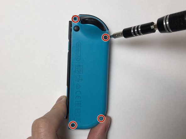
    • Use the Tri-indicate Y00 screwdriver to remove the four six mm screws from the back of the Joy-Con.

  2. Insert the opening pick into the bottom of the Joy-Con, then move it towards the L and ZL buttons. Lift the back shell off the Joy-Con and place it to the side. Be careful when removing the back shell as it is connected to two ribbon cables  by the charging rail and motherboard. Potential for device damage may occur if it is yanked apart.

    • Insert the opening pick into the lesser of the Joy-Con, then motion it towards the Fifty and ZL buttons.

    • Elevator the back vanquish off the Joy-Con and place it to the side.

    • Be conscientious when removing the back trounce as it is connected to ii ribbon cables by the charging track and motherboard. Potential for device damage may occur if it is yanked apart.

  3. Insert a spudger or prying tool beneath the battery wires and gently pry the battery plug out of the socket on the motherboard. Once the battery plug is removed from the socket, lift the battery off the mid-frame. A spudger is recommended for this step if one is available. If not, use an ESD safe tool.

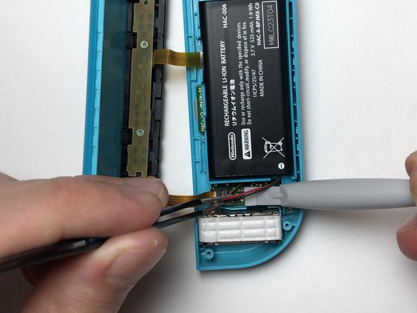
    • Insert a spudger or prying tool beneath the battery wires and gently pry the bombardment plug out of the socket on the motherboard.

    • In one case the battery plug is removed from the socket, lift the battery off the mid-frame.

    • A spudger is recommended for this step if one is bachelor. If not, apply an ESD safe tool.

  4. Unscrew the three golden 3 mm Phillips #000 screws holding the mid-frame in place. Lift the mid-frame off the motherboard and place it to the side. Lift the mid-frame off the motherboard and place it to the side.

    • Unscrew the three aureate 3 mm Phillips #000 screws holding the mid-frame in identify.

    • Lift the mid-frame off the motherboard and identify it to the side.

  5. Unlatch the ZIF connector that is locking the ribbon cable on the mid-frame to the motherboard. Use tweezers to gently pull the ribbon cable out of the ZIF connector. Use tweezers to gently pull the ribbon cable out of the ZIF connector.

    • Unlatch the ZIF connector that is locking the ribbon cable on the mid-frame to the motherboard.

    • Use tweezers to gently pull the ribbon cable out of the ZIF connector.

  6. Unlatch the two ZIF connectors that are locking the ribbon cables on the charging rail to the motherboard. Use tweezers to gently pull the ribbon cables out of the ZIF connectors. Use tweezers to gently pull the ribbon cables out of the ZIF connectors.

    • Unlatch the ii ZIF connectors that are locking the ribbon cables on the charging track to the motherboard.

    • Use tweezers to gently pull the ribbon cables out of the ZIF connectors.

  7. Remove the 2 mm Philips #000 screw holding the  charging rail onto the back shell. Remove the charging rail from the back shell. There is an adhesive tape that helps keep the charging rail in place on the back shell. When placing the new charging rail onto the back shell, it is advised to also replace the adhesive to add extra support, but it is not essential.

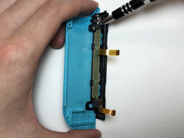
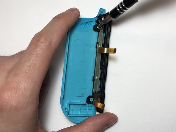
    • Remove the 2 mm Philips #000 spiral property the charging rail onto the back shell.

    • Remove the charging rail from the back beat.

    • There is an adhesive tape that helps keep the charging rail in place on the back shell. When placing the new charging rails onto the back vanquish, it is advised to also supplant the adhesive to add together actress back up, just it is not essential.

  8. Use the Phillips #000  screwdriver to remove the two 3 mm screws at the center of the PCB. Remove the PCB from the charging rail.

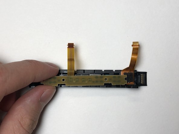
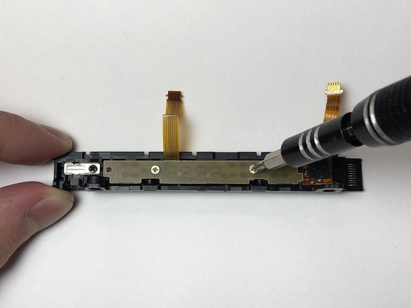
    • Employ the Phillips #000 screwdriver to remove the two 3 mm screws at the center of the PCB.

    • Remove the PCB from the charging runway.

  9. Remove the SL, SR and sync buttons from the charging rail. Remove the SL, SR and sync buttons from the charging rail. Remove the SL, SR and sync buttons from the charging rail.

    • Remove the SL, SR and sync buttons from the charging rails.

  10. Place the SL, SR and sync buttons into the new charging rail and make sure the tabs on the SL and SR buttons fit into their respective socket grooves. Place the PCB over the buttons and secure it in place using the two golden 3 mm Phillips #000 screws. Potential for device damage. If the buttons are not properly placed into the charging rail, proceeding to screw in the PCB will cause it to warp.

    • Place the SL, SR and sync buttons into the new charging rail and brand sure the tabs on the SL and SR buttons fit into their respective socket grooves.

    • Place the PCB over the buttons and secure information technology in place using the ii golden 3 mm Phillips #000 screws.

    • Potential for device damage. If the buttons are not properly placed into the charging rail, proceeding to screw in the PCB will cause it to warp.

  11. Align the charging rail with the two standoffs on the back shell. Secure the rail onto the back shell using the 2 mm Phillips #000 screws.

    • Align the charging rail with the two standoffs on the back beat out.

    • Secure the rail onto the back shell using the two mm Phillips #000 screws.

  12. Use tweezers to insert the ribbon cables  for the charging rail into the ZIF connectors on the motherboard. Press down on the latch for each ZIF connector to secure the ribbon cables in place. Press down on the latch for each ZIF connector to secure the ribbon cables in place.

    • Utilise tweezers to insert the ribbon cables for the charging rails into the ZIF connectors on the motherboard.

    • Press downward on the latch for each ZIF connector to secure the ribbon cables in identify.

  13. Use tweezers to insert the ribbon cable for the mid-frame into the ZIF connector on the motherboard, with the golden pins facing upwards. Press down on the ZIF connector latch to secure the ribbon cable in place.

    • Use tweezers to insert the ribbon cable for the mid-frame into the ZIF connector on the motherboard, with the gold pins facing upwards.

    • Printing down on the ZIF connector latch to secure the ribbon cablevision in place.

  14. Place the the mid-frame over the motherboard. Using Philips #000 screwdriver, secure the three golden 3 mm screws of the mid-frame onto the motherboard.

    • Place the the mid-frame over the motherboard.

    • Using Philips #000 screwdriver, secure the three gilded 3 mm screws of the mid-frame onto the motherboard.

    • When placing the mid-frame onto the motherboard, the bumper push button may come loose. To reattach the bumper push, first insert the jump on the bumper button into the groove located on the top left side of the Joy-Con, and so insert the right side of the bumper button into the Joy-Con.

  15. Place the battery into the mid-frame. Use tweezers to align the battery plug over the socket and with a pry tool or an object with a flat edge, press the plug into the socket.

    • Identify the battery into the mid-frame.

    • Use tweezers to align the battery plug over the socket and with a pry tool or an object with a flat edge, printing the plug into the socket.

  16. Align the charging rail into the notch on the left side of the Joy-Con. Apply even pressure on both sides of the Joy-Con until the two shells click together. Screw in the four 6 mm Tri-point Y00 screws into the back of the Joy-Con.

    • Align the charging runway into the notch on the left side of the Joy-Con.

    • Utilise even force per unit area on both sides of the Joy-Con until the two shells click together.

    • Spiral in the four six mm Tri-point Y00 screws into the back of the Joy-Con.

Team

Embed this guide

Choose a size and copy the code below to embed this guide every bit a modest widget on your site / forum.

Preview

Source: https://www.ifixit.com/Guide/Left+Joy-Con+Charging+Rail+Replacement/142938

Posted by: larsonexampations.blogspot.com

0 Response to "How To Open And Repair 36v Sla Charger"

Post a Comment

Iklan Atas Artikel

Iklan Tengah Artikel 1

Iklan Tengah Artikel 2

Iklan Bawah Artikel